How Do You Terminate Connections on Flex PCBs?
Terminate Connections on Flex PCBs
During the past 30 years we have seen dramatic changes in the size of electronic devices. The reason for this is a number of innovations, but the most important is flexible PCBs. Flex PCBs are much thinner than rigid PCBs, and offer significant amounts of design flexibility, allowing for lighter, smaller, and more compact products.
flex pcbs are made from a flexible base material, typically polyimide. This material is very tough (you can’t noticeably tear it by hand) and incredibly heat resistant. This means that they are tolerant of the solder reflow cycles used in product assembly, and they are stable in terms of expansion and contraction with temperature fluctuations.
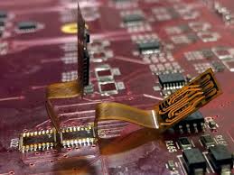
The most common method for connecting a flex circuit to a rigid PCB is by soldering. This is done by creating a set of pads on the rigid PCB that line up with a set of pads on the end of the flex, and then joining them by soldering to each other. This can be a good solution, especially for simple assemblies. For more complex applications, however, it is recommended that a flexible glue be applied between the two boards.
How Do You Terminate Connections on Flex PCBs?
There are several other ways that flex PCBs can be connected to a rigid board. One is to use an adhesive such as epoxy or acrylic. This is often the preferred method because it provides the best structural integrity. Another option is to use a mechanical fastener such as a crimp connector system. These systems allow for easy access to wiring or custom harnesses, and come in a wide variety of male and female mating options. They also feature centerline housings to encapsulate the contacts.
Regardless of the type of connection, it is always important to properly terminate connections on flex PCBs. This is because a proper termination can help reduce signal loss and improve compatibility with other systems. For example, properly matching a signal’s impedance with the receiver can minimize losses and improve signal transmission efficiency.
In the realm of modern electronics, flexibility is not just a desirable trait; it’s becoming a necessity. With the constant push towards miniaturization, portability, and innovation, traditional rigid printed circuit boards (PCBs) are often too limiting. Enter flexible PCBs, the game-changers of electronic design and manufacturing.
Flexible PCBs, often referred to as flex circuits or FPCs, represent a paradigm shift in electronic engineering. Unlike their rigid counterparts, which are made of inflexible materials like fiberglass, flexible PCBs are constructed using flexible plastic substrates such as polyimide (PI) or polyester (PET). These substrates allow the circuits to bend, twist, and conform to the shape of the devices they power, opening up a world of possibilities for designers and engineers.
Before adding any connectors or other attachments to a flex PCB, it’s important to clean both surfaces with isopropyl alcohol and a lint-free cloth to remove any debris that could interfere with the electrical connection. It is also important to remember that flex circuits are more sensitive than rigid ones, so they should be handled carefully. Moreover, it’s recommended that a layer of non-conductive epoxy or silicone be added between the flex and the connector to protect the copper and make it less likely to damage the board.